Chapter 3 Hardware
This page describes how to build a Sticky Pi. It involves familiarity with 3D printing, electronics, DIY, … First, we present an short overview of the device itself. Second, we describe the “assembly graph” to construct it from basic parts. Third, we present the minimal attachments/modules needed to test abd operate it (battery, sticky card holder). We are working on streamlining the assembly process towards a more ‘off-the-shelf tool’, but are generally happy to collaborate and help building devices – do not hesitate to contact us.
Overview
As shown here, Sticky Pis have two main part, the camera box, which contains all the electronic and the camera, and the lightbox, which works like a backlight when images are taken. These two parts are connected by metal rods.
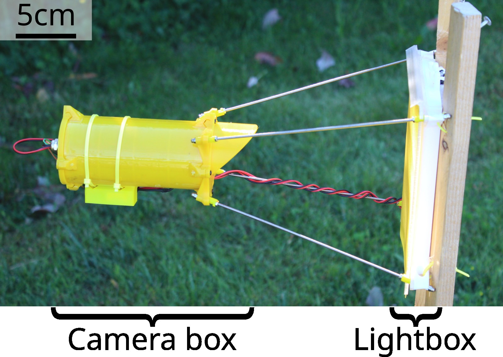
Figure 3.1: Assembled and deployed Sticky Pi, version 2
The complete list of parts and consumables required (i.e. Bill Of Material) is available here.
Custom Board
The first part is a custom board, the Sticky Pi Hat, that we designed to simplify the assembly process. This board has its own BOM. The KiKad project (including schematics) and Gerber files are available here. The Sticky Pi Hat and can be readily machine-assembled in a factory. We are happy to assist users with ordering.
3D-printed parts
All 3d printed parts are available on our Onshape repository. Snapshots of individual stl files are also on our github here
Assembly graph
We decided to describe the assembly process as an interactive graph. The assembly process goes from the top down. Each part is a rectangle on which you can click to access its documentation. Each diamond shape, is a “process” on which you can click to show a video and written description. You can also use the search bar to find parts or processes. Here is an example showing how to use this interactive documentation.
![]() Interactive building instructions
Interactive building instructions
Navigate and click on the graph to display instructions
Modules
In addition to the Sticky Pi itself, in most cases, you will need a power module (e.g. a battery), and a support to hold sticky cards. Here, we describe these two essentials, as well as the station we designed to test devices.
Battery module
Sticky Pis can accommodate various power solutions – as long as you provide 3.5-6V continuous current, and at least 500mA. Power needs to be provided through a female 2-pin auto connector (that matched the sticky Pi male connector), often you would just buy them in pairs. What battery you pick depends on your use case, In some cases you can also adapt a USB cable to provide 5V to sticky pis without a battery (e.g. in a lab or a green house). The top of the lightbox exposes a flexible attachment we intended for batteries.
In most of our use cases, we opted for off-the shelf tablet lithium ion batteries such as this one. Then we encased the batteries battery in epoxy with custom pegboard pins to hang the it on the light box:
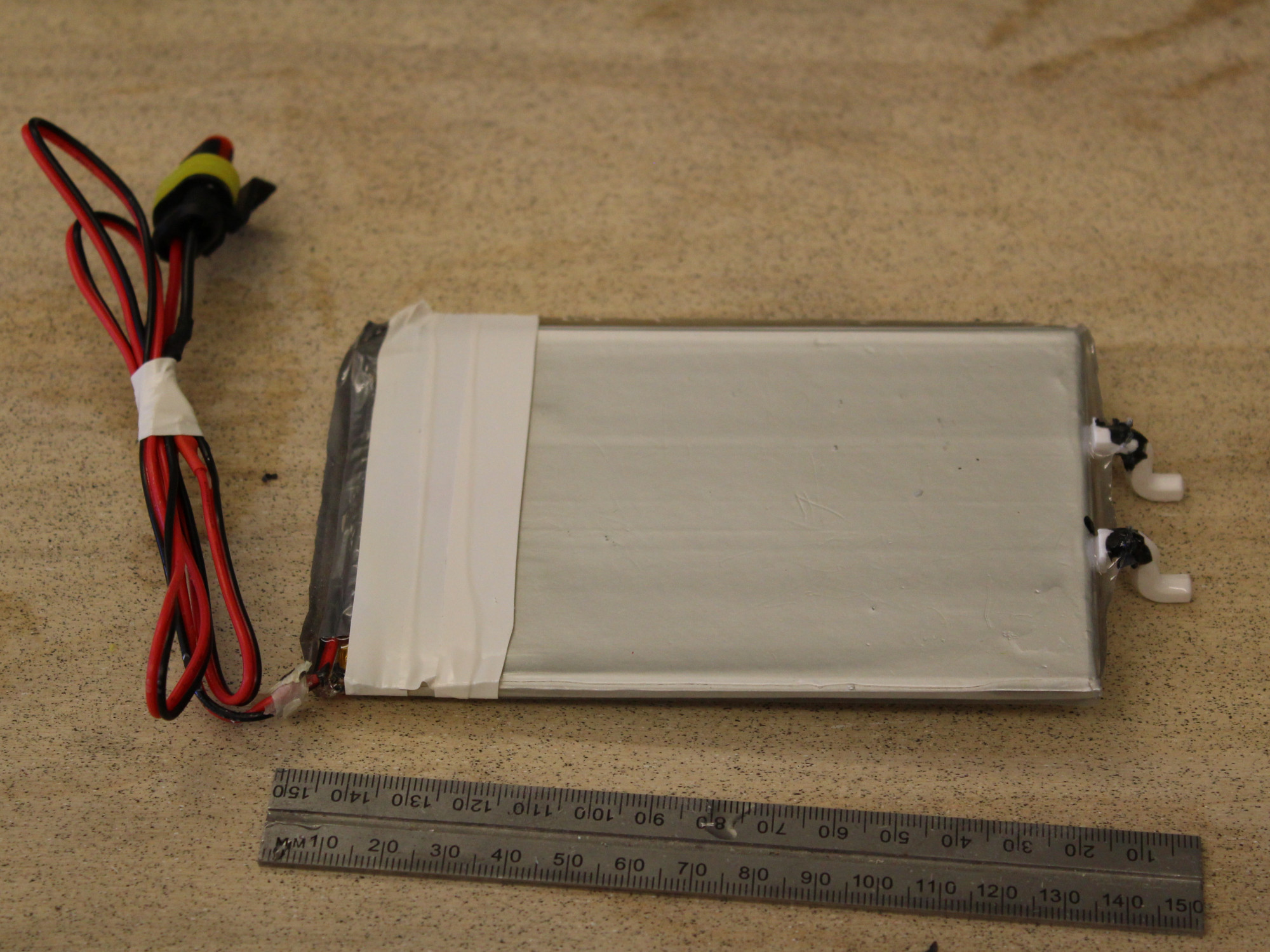
Figure 3.2: Battery module
In order to charge the batteries, we modified solar panel chargers:
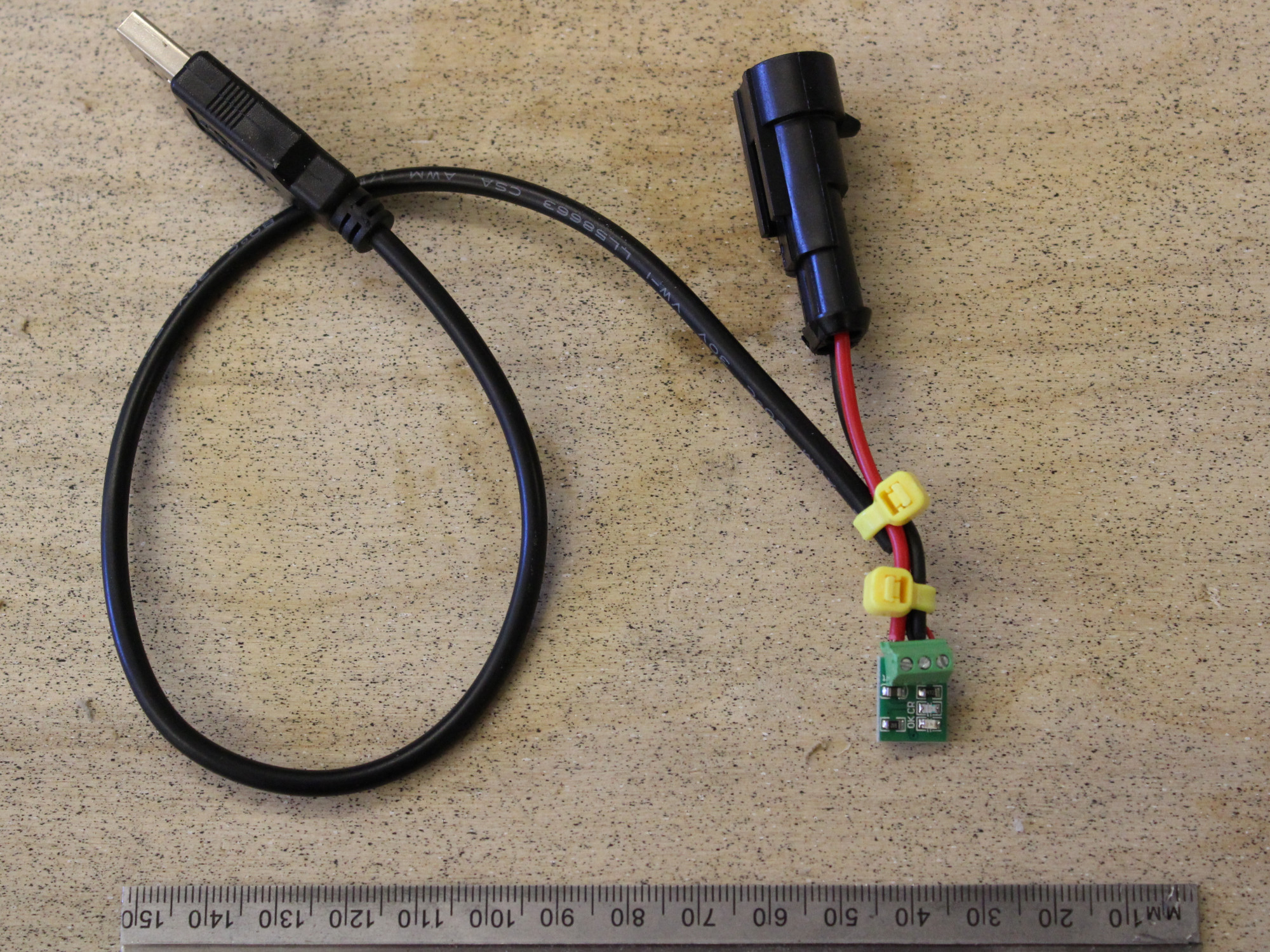
Figure 3.3: Simple battery charger
In our experience, 5000mAh batteries lasted approximately 10 days (depending on the weather).
Sticky Card Drawer
Instead of sticking sticky cards directly on the lightbox, we strongly recommend using “drawers” on which you can pre-stick a card and swap drawers in and out. The printed drawers look like this:
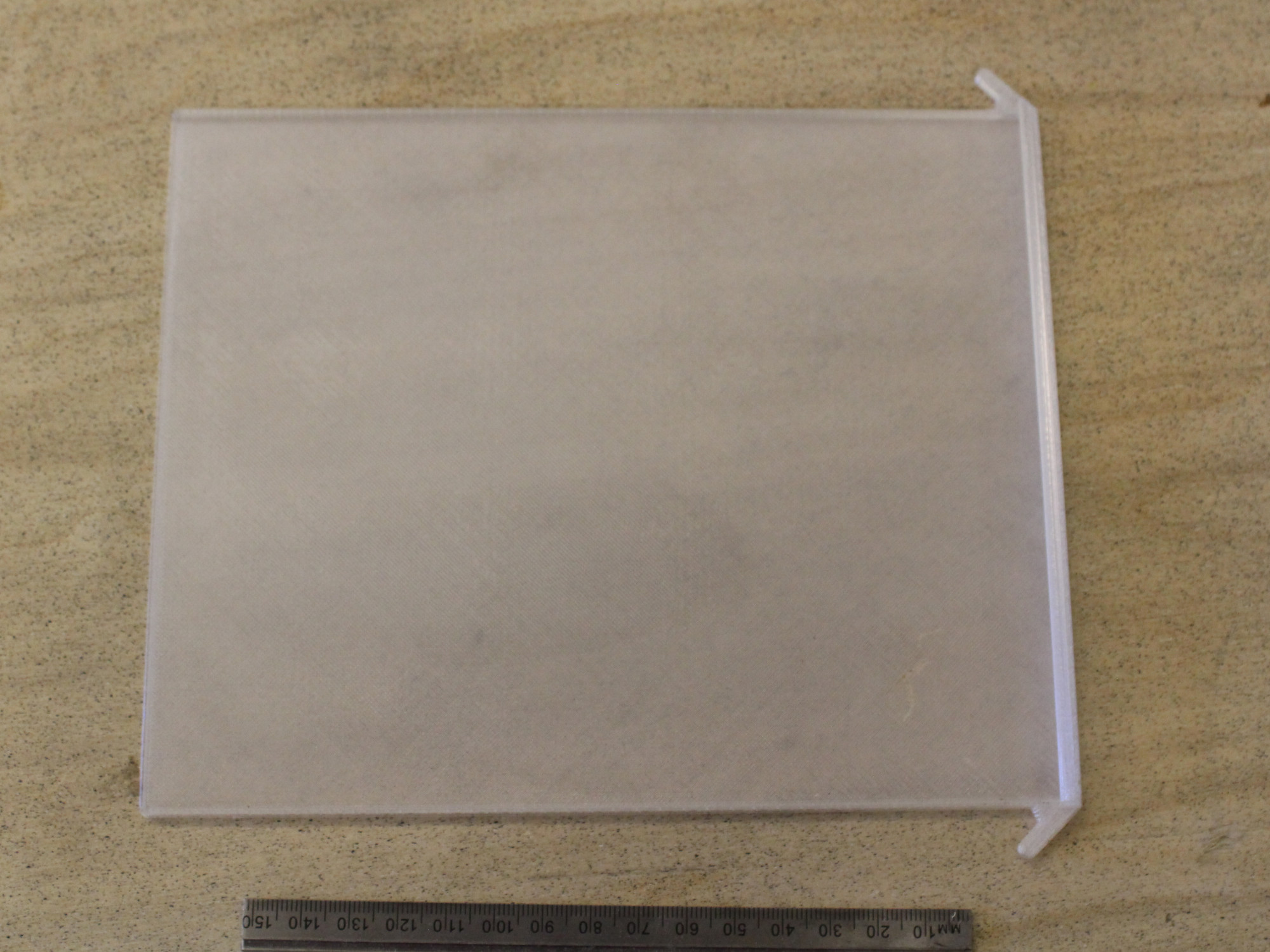
Figure 3.4: Sticky card drawer
The part for the drawer is available on our Onshape repository. You can also just download the STL file. Note that you need a transparent material. You can also make a drawing from the Onshape part and laser-cut a of acrylic to do the job.
Testing Station
The testing station is used to adjust the focus of devices. It consists of two main parts: a testing tower, on which the “sledge” rests, and a perpendicular plane at the same distance as the sticky card would be:
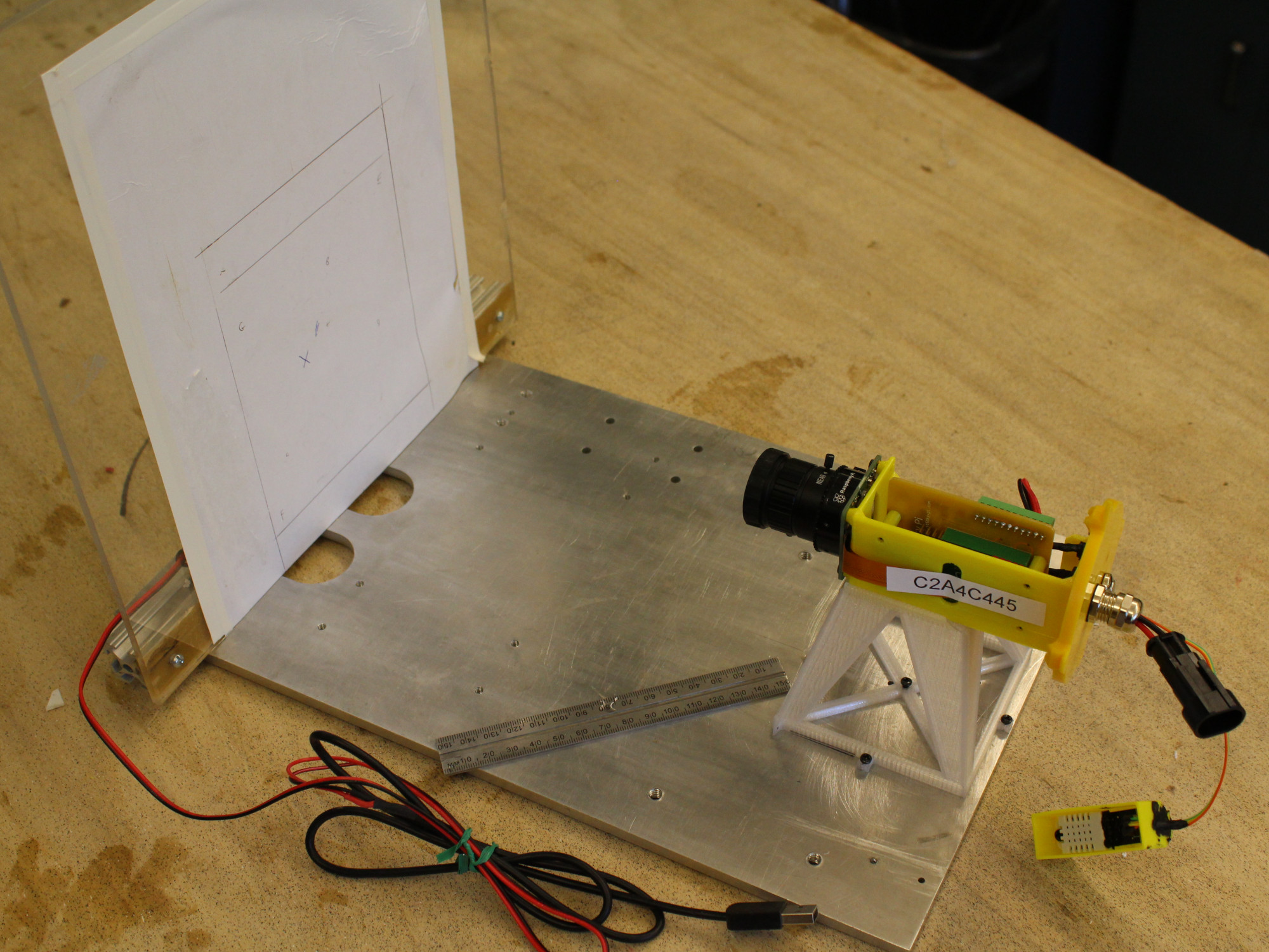
Figure 3.5: Sticky Pi testing platform
To adjust the camera’s aperture, we can attach a lightbox in the back of the vertical wall ad manually turn it on with a modified USB cable. The precise dimensions of this platform are available on Onshape.